Geo Clustering exists in many options, and dependent highly on the requirements and technical capability. This post is to discuss some options and things to consider before deploying any geo-cluster.
Data GEO- Redundancy
The first dependency in clustering is storage capability. Data from the workload in the cluster will be written to disk and that data needs to be available on both sites. Within Microsoft SQL AlwaysOn can replicate the data for the instances and ensure it is available on both sites. It is also possible to have the storage perform data mirroring.
When sending data from site A to site B, two options exist: Synchronous and A-Synchronous.
Synchronous: Data is written to BOTH sites before the application or server receives a successful write notification
A-Synchonous: Data is written to the primary site, the application or server receives the write, and THEN the data is written to the second site.
Within a synchronous architecture, there is very limited chance of data-loss upon a failure, as the application knows the data is written in two locations. With A-synchronous data loss can occur.
While synchronous looks most tempting, it requires fast connections between the storage / servers in order to reduce latency for every I/O write action. Therefore this is not always possible and a-synchronous is the only option left.
Storage mirroring or AlwaysOn data replication must be used to provide data geo-redundancy
LUN Assignments
When Storage LUN’s are being used in a geo-cluster, the LUN assignment is critical to the cluster setup.
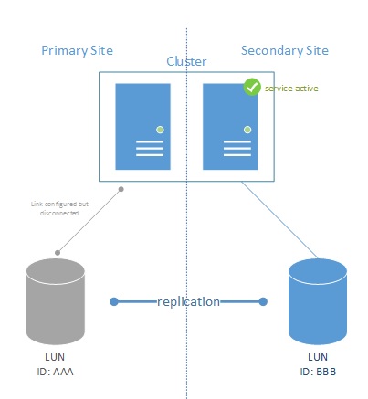
Figure 1

The figure (1) above shows a typical geo-replication setup for SAN based storage. Each storage unit has its own LUN created and the LUN ID’s are different on both sites. Replication is setup (one way) between LUN AAA to LUN BBB. The cluster itself is connected to LUN AAA with an active path. LUN BBB is actually disconnected in order for the storage to be able to provide the replication to LUN BBB.
If the primary site fails, LUN BBB needs to be activated, and the cluster will connect to the storage for usage.
Figure 2
Upon such activation, the replication is usually stopped. LUN AAA will be fully disconnected from the cluster and LUN BBB will be activated and connected to the cluster to continue working. As replication does not need to happen in real-time, and activation required manual intervention, sites can be connected through low-latency connections.
NOTE: Services on the cluster WILL temporarily loose storage connectivity while the secondary LUN (LUN BBB) is activated.
NOTE2: This setup requires 3rd party plugins or manual activation during failover
Virtual LUN’s or vDisks
Some storage providers provide a technology to provide the same LUN ID to both sites. In that architecture, where the storage is active does not really matter. All nodes see the same LUN ID and it is up to the storage to determine the actually active LUN.
Figure 3
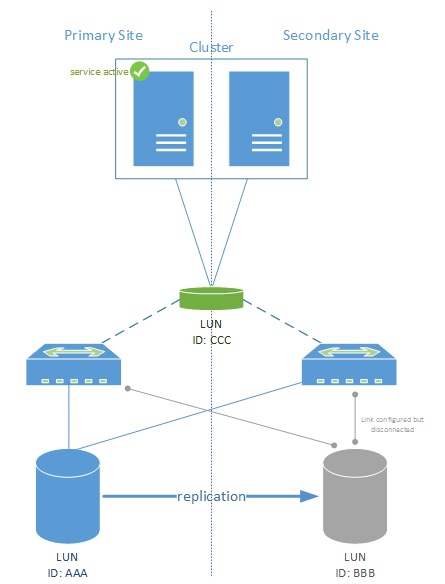
In this case, the LUN itself is “virtualized” and represented to both nodes. Thus the secondary site will see the storage as online storage and can instantly take over the workload of the primary site. This separates the workload on the cluster from the actual active storage LUN.
If the storage itself has a problem and the primary site goes down, the storage directors will failover and automatically activate LUN BBB. It does not mean that the activation of LUN BBB implies the active service on the clusters also fails over. I/O to the storage is simply sent cross site in that case. 3rd party plug-ins (or storage plugins) may force the workload to failover to the secondary site in case that happens.
NOTE: As I/O can go travel cross-site, a high bandwidth low latency connection between the two sites will be required. Usually this is a dark-fiber connection and the sites are <10km apart.
Automatic Failover
Clusters are used to provide a highly-available service. This usually implies an automatic failover of the hosted service. In order to help decide a cluster to choose which site is responsible for a workload, a quorum is used. The quorum can be setup by number of nodes in a cluster (node majority) or a third party component.
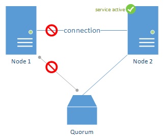
Figure 4

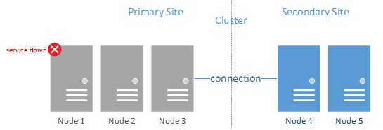
Under normal conditions, each cluster node is connected to other cluster nodes. This connection allows the nodes to communicate about the workload and who is actively serving it. If node 1 would not be available, node 2 must now take over the workload. However, in the above picture, Node 2 cannot determine if it is the connection between them that has failed, or indeed Node 1 as we just assumed.
In an even number of nodes cluster, an external voting mechanism is used.
Figure 5
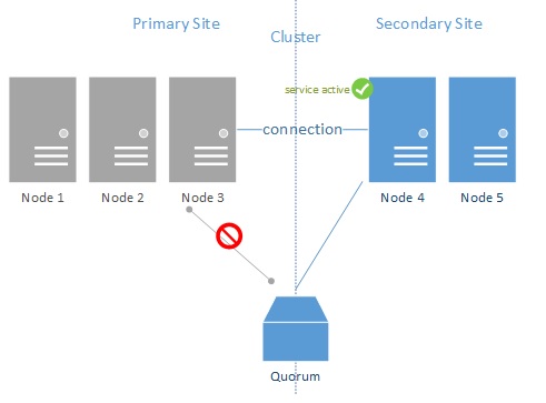
In the figure above (5), Node 2 has lost communication with Node 1. It uses the quorum to determine where the problem is. Since Node 1 has also lost communication with the quorum, Node 2 is instructed to take over the workload.
Note: In an even number of node clusters, a quorum MUST be configured.
When more nodes are added to the cluster, node majority can be used. Each cluster node communicates with all the other nodes, and as soon as the active Node loses connection, it counts the cluster Nodes it can still reach. If that number is the majority of servers, it knows it can still have the active workload.
Figure 6
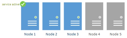
This architecture works well within a single site, but as soon as the cluster is geographically dispersed, another layer of complexity is introduced. When Node 4 and Node 5 would be in de secondary site, both are now reliant on the cross site network connection.
Figure 7
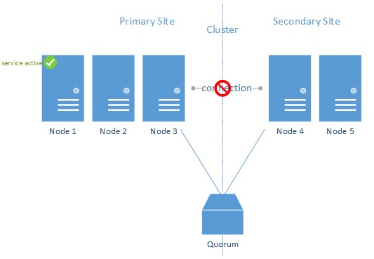
In figure 7, the primary datacenter failed. While the connection could still be alive, the nodes in the secondary sites will not activate the service as they do not have the majority of the nodes. In this configuration (node majority only) the entire cluster will fail and the workload will not be activated.
This means that in Geo-Clusters there should always be a quorum configured. It is vital that this quorum is configured on a third site. Else, automatic failover would not occur.
It is still possible to create the cluster with a quorum on a single site, however, manual activation of the service will be required, and detailed planning of the workload needs to be completed. For example, if the quorum would be in the secondary site, but the workload is active in the primary site, the loss of a connection between the sites will result in an immediate failover as the secondary site has the quorum access. Having the quorum on the same site as the workload will ensure the workload stays online, but during a failure of the primary site, manual intervention (reconfiguring a quorum on the secondary site) will be required to restore cluster functionality.
Quorum choices
Two choices exist for the quorum, a quorum disk or a witness folder. The quorum disk is a LUN provided by the SAN storage that nodes directly attach to. By determining who has access to the LUN, the ownership can be determined and hence if a node is still on-line or not.
However, when a LUN is chosen, it must not be a vDISK. In that scenario the storage controllers responsible for creating the vDisk will also be on that particular site. This means it is not a 3rd party site. With that said however, most vDisk implementations already use a 3rd site witness SAN which acts as the quorum for the storage solution itself. This SAN is usually a small SAN that is also capable of providing LUN’s. A quorum disk from that SAN might be used if the connections to that site allow for this.
Another option is to use a file share witness. A file server in a remote site is used as the quorum. This file share might be available through a layer 3 network connection and can even be a slow remote link. The folder itself is not used for writing extensive data in and will only be used in the case of communication errors between the primary and secondary site; or when a failure on one of the sites occurs.
Figure 8
In figure 8, it is visible, that while there is no Node majority, the Secondary site servers can still connect to the quorum and activate the service.
In figure 9 the connection between the sites is broken, while the primary site is still online and active. Although the secondary site would not be able to detect the three nodes in the primary site it checks the quorum and identifies that the nodes are still online and responding. Therefore there won’t be a failover for the service.
Figure 9
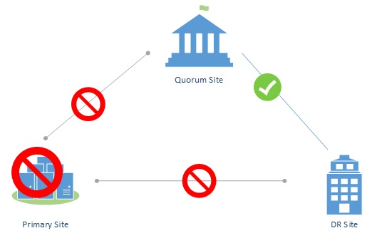
As the quorum determines whether or not a site is up or down, the quorum must reside in a third site. This site must be fully accessible by the primary site AND the secondary site. The most common mistake made is that all traffic is routed through the primary site in a hub and spoke setup. In that case, the loss of the hub site, would result in losing all connections and thus no automatic activation of the cluster. Therefore, the traffic from DR to the quorum site must never be routed through the primary site.
Figure 10
Network
Now while the cluster itself can be geographically dispersed, it doesn’t mean the actual clients using it can use the geo-clustered architecture. It highly depends on the network capabilities that can be provided on network level.
Layer 3: if Layer 3 networking is provided, it means the subnet on the primary site for the cluster differs from the IP address of the cluster in the secondary site. Basically this means that when a failover occurs, the IP address of the cluster and the workload changes.
Figure 11
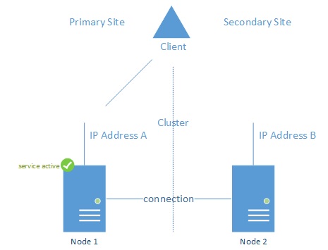
In figure 11, clients are connected to IP Address A belonging to the cluster in the primary site. This is also where the active workload currently is. Clients connecting to IP address B will not be served as the workload is not hosted on Node 2.
When a failover occurs, clients will need to reconnect to IP address B. which in itself is not a problem, but, clients cache the service name FQDN to IP address mapping. For example, if the service is hosted on myservice.contoso.com, clients will request the IP address of that service from the DNS service. The DNS service itself will provide (by default) both IP addresses and it is up to the client to determine which address is actually active (SQL Server 2012 Client will automatically do this).
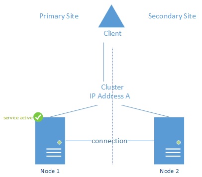
Layer 2: If Layer 2 networking is possible, it means that the network subnet spans the primary and secondary site. It means IP addresses can either be active on the primary site network or on the secondary network. It simplifies the setup and management of the cluster as during a failover the IP address does not change. Clients do not need to be aware of failovers that happen on the cluster itself.
Figure 12
Conclusion
Designing a cross site cluster is not as easy as it looks. There are many variations and technical requirements, but if the secondary datacenter is close, the lines between the datacenters are fast, layer 2 networking is available and there is a third site that can act as a witness, it would be easier to implement an active-active datacenter setup where it does not matter where which application is active.